Designing and 3D Printing a ZMR250 Quadcopter Spacer
A walk through of the design and 3D Printing of a custom spacer for the popular ZMR250 quadcopter frame. Designed using OpenSCAD and Printed using an Original Utlimaker 3D Printer.

I have recently (for the last 6 months) become more and more interested in building multirotors, specifically quadcopters.
It seems like a good fit for me as it combines radio control, hacking/making, electronics, racing and programming.
After watching Bruce Simpsons YouTube series on building a cheap racing quadcopter I felt ready to try build my own.
I settled on the ZMR250 frame, which is a very popular choice in the hobby.
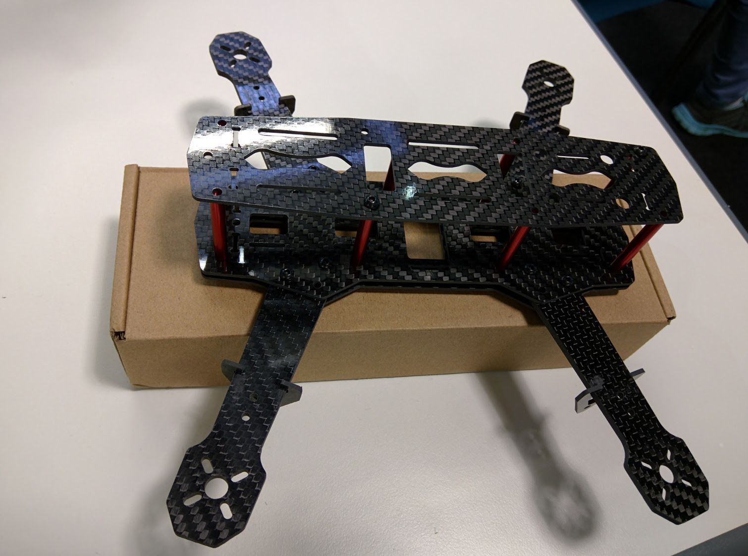
The normal build strategy is to keep the quad in the arrangement in the picture above and then to put most of the components on top of the middle plate (the upper of the 2 bottom plates) and to then put the battery, recording camera and video receiver on top of the top plate.
I bought my frame a month or two before I bought the rest of the parts to build the quad. While sitting with the frame, I began to think about better ways to fit everything into the quad. I didn't like the idea of putting the battery on top of the quad, as it would then be top heavy and the battery would be unprotected in a crash.
As a software developer, I am inclined to not "roll my own" solutions from scratch, until I have seen if anyone has already done something similar that I could use first. This sounds like laziness, but after the 4th or 5th time of spending hours building something to find one online that does it better than yours, you tend to avoid reinventing the wheel.
I found a few designs on Thingiverse where people had created spacers to go between the bottom 2 plates so that more components could fit between them and thereby create more space for other things between the top and middle plates.
I first printed out the Uni-spacer from alexnovik.
This spacer was really nice, but it had some issues which made it not ideal for what I wanted.
When my parts arrived, I noticed that the XT60 connector at the back of the quad was not a good idea. when the battery was plugged into it, the battery was too far back and would throw off the centre of gravity.
I also noticed that since I got the Naze32 revision 6 instead of the revision 5 that this spacer was designed for, the USB cut-out was in the wrong place.
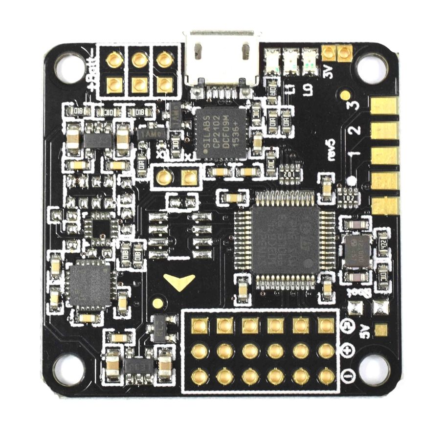
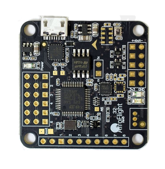
images nicked from radioc.co.uk
Also, when the servo connector pins where soldered in to connect the ESCs to the flight controller, the top of the board was about 12mm high, but this spacer was only 10mm high.
So with all of these things making the spacer not work for what I wanted, I decided to look for one that did.
I looked for a long time, but I didn't find anything that suited what I needed exactly.
The closest I found was the non-cutout version of swilkens' Slim Buid Spacer.

This one still had its problems, but it was a good base to work from to create my own.
I used OpenSCAD to import swilkens' design and modify it.
import("/home/jayd/3D\ prints/Spacer_V1.0_no_cuts.STL", convexity=3);
The first thing I needed to do was to cut the frame down to 12mm so that it was the correct height for the flight controller and the pins that I was using. I wrapped each OpenSCAD section in its own module so that I could use it easily in the next section.
module shortened() {
    difference() {
        translate([0,0,12]){
            difference() {
                rotate([-90,0,0]) {
                    import("/home/jayd/3D\ prints/Spacer_V1.0_no_cuts.STL", convexity=3);
                }
                translate([0,0,-22]) {
                    cube([200,200,10]);
                }
            }
        }
    }
}
shortened();
I then realised that all the other modifications would have to be done 4 times to maintain the symmetry so I decided to quarter the model.
module quarter() {
    difference(){
        shortened();
        translate([0,95,0]){
            cube(150,150,20);
        }
        translate([34,0,0]){
            cube(150,150,20);
        }
    }
}
quarter();
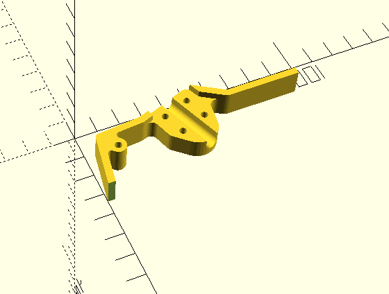
The space between the arm connector blocks was very small. I wouldn't have been able to fit the RC Receiver into that space, so next I needed to make that space bigger.
module cut_out() {
     difference() {
        quarter();
        translate([23,35,0]) {
            rotate([0,0,20]){
                cube([22,22,12]);
            }
        }
    }
}
cut_out();
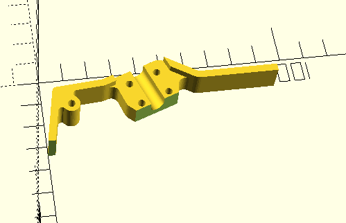
I plan to put LEDs on the quadcopter at some point. I wanted a space to run some more cables around the inside of the spacer where it didn't interfere with the ESC cables or the RC receiver, so I created a small channel for the wires to run, on the other side of the arm connector block.
module wire_channel() {
    difference() {
        cut_out();
        translate([15,30,0]){
            rotate([-90,0,12]) {
                cylinder(r=2, h=28);
            }
        }
        translate([30,73.2,0]){
            rotate([-90,0,130]) {
                cylinder(r=2, h=28);
            }
        }
    }
}
wire_channel();
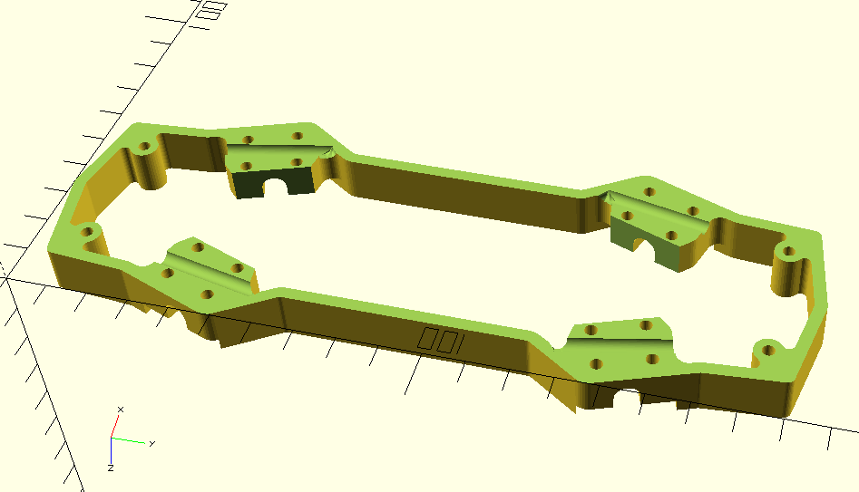
With all of the symmetrical changes done, I needed to rebuild the spacer model.
module half() {
    wire_channel();
    translate([0,185,0]){
        mirror([0,1,0]) {
            wire_channel();
        }
    }
}

module new_frame() {
    half();
    translate([68,0,0]){
        mirror([1,0,0]) {
            half();
        }
    }
}

new_frame();
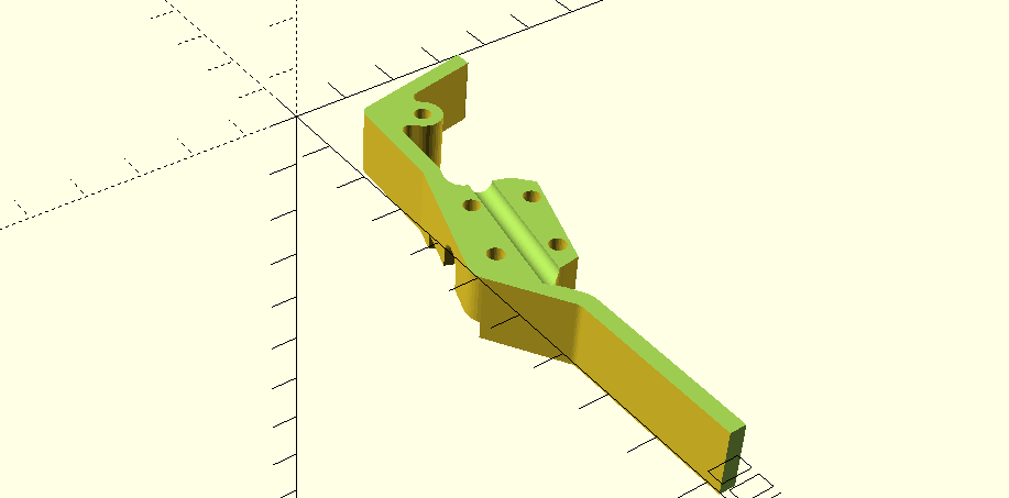
The last modification to be made was a cut-out in the correct location for the Micro USB port on the Naze32 revision 6 flight controller.
module frame_cut() {
difference() {
new_frame();
translate([52,79,4]) {
cube([10,12,9]);
}
}
}
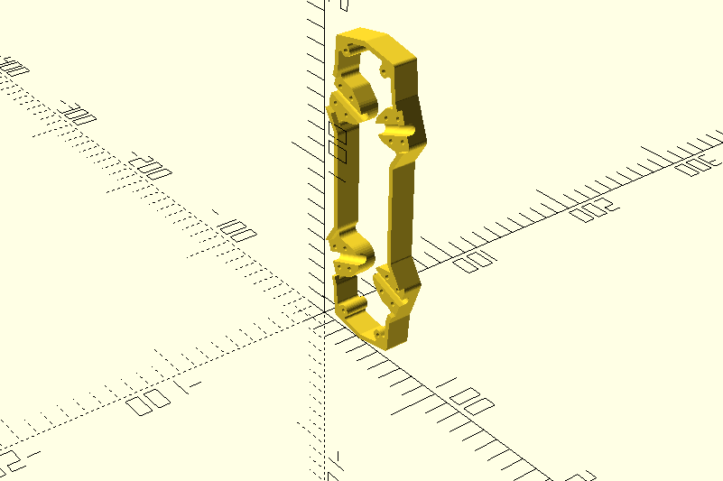
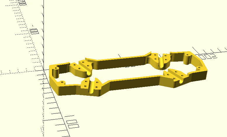
frame_cut();
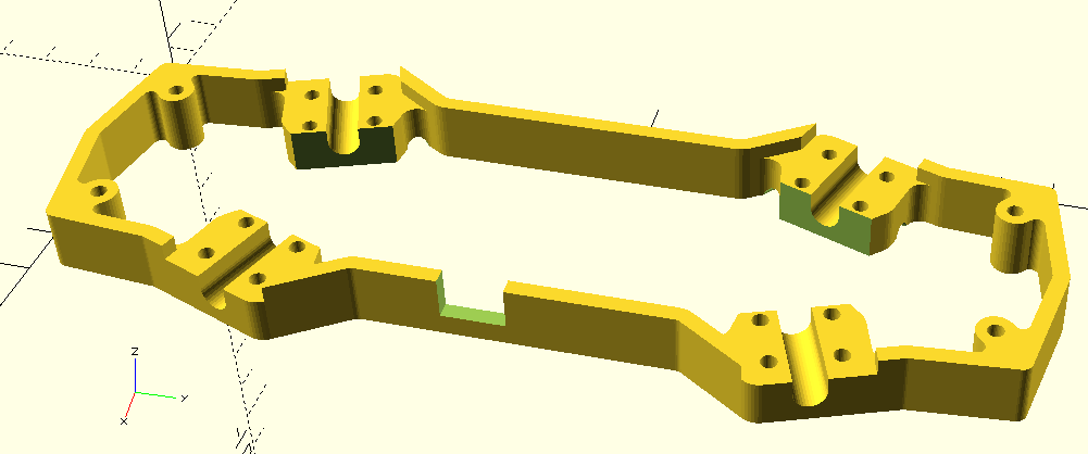
And with that, the frame was ready for printing, I just needed to "Export as STL" from OpenSCAD.
The full OpenSCAD design can be downloaded from this GitHub Gist.
I have also uploaded the resultant .STL file to thingiverse, if you would like to skip straight to downloading and printing it.
Later I moved to the Seriously Pro F3 flight controller which has the Micro USB in a different place, I also uploaded that one to Thingiverse.
I am part of the Preston Hackspace Group, so I had access to a 3D Printer. Ultimaker have lent us one of their original Ultimaker 3D Printers, which I used to print out this part. The printer did not have a heated bed, so the spacer is printed in PLA.
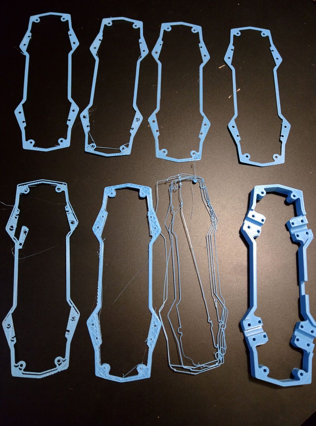
3D Printing the model was a bit problematic. I managed to print it on my 8th attempt.
The model is designed to be printed upside down, so that the new wire channels are at the bottom, like it is in the last OpenSCAD screenshot above.
The problem that I encountered while printing is that the printer would print the outline of the frame with no issues. But then when trying to print the separate "island" tabs which where the other halves of the arm connector blocks on the other side of the new channels that I created, they would not stick properly to the printing bed and the print would have to be aborted. This could be easily sorted out by using a heated printing bed. I didn't have access to a heated printing bed, so I ended up setting a slower print to get it to stick on the first layer.
I also had an issue that after a few layers, the same problematic "islands" would be bumped by the print head and separate from the printing bed. This was mainly caused because of the tendrils left when the printer finished printing in one place and moved over to another area, without retracting enough filament. This can be fixed by adjusting the amount that the filament is retracted when the print head moves over open space.
The final issue that I had was that one of the pulleys came loose at the stepper motor. This can be seen on prints 5 and 7 in the image above. The print would go well and then part way through, while moving the head over open space, the tracking would be lost and it would start printing slightly off, ruining the print.
I tracked down the loose part by marking all the axles with a marker, doing a quick print and seeing which of them moved. I found the problematic part and tightened it and finally the part was printed.
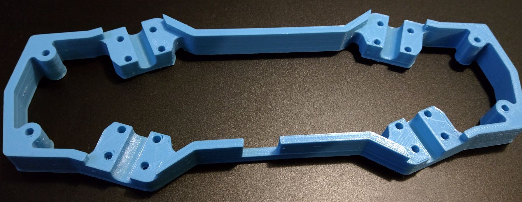
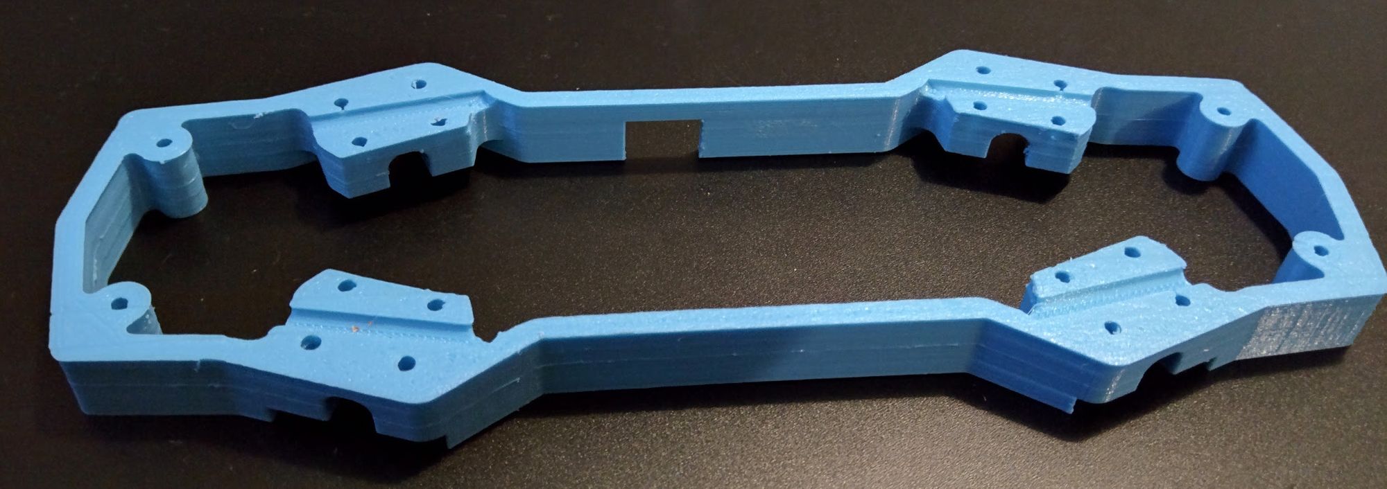
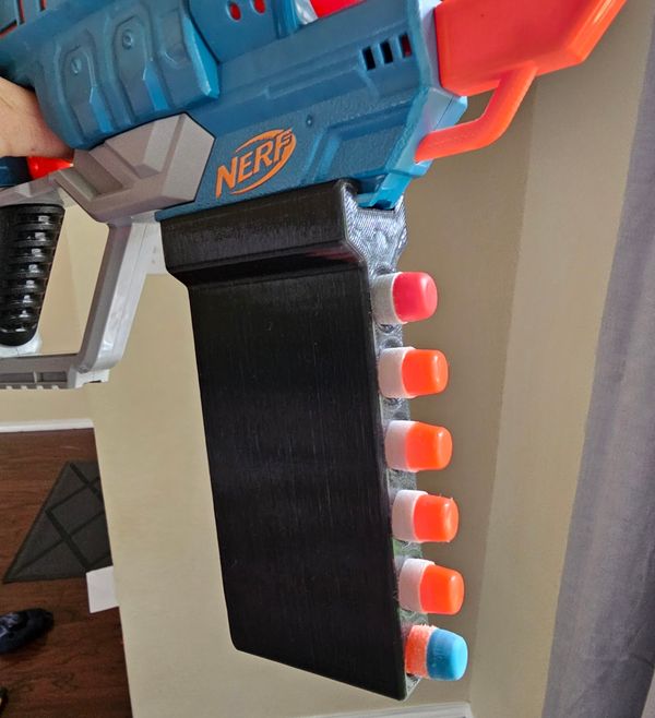
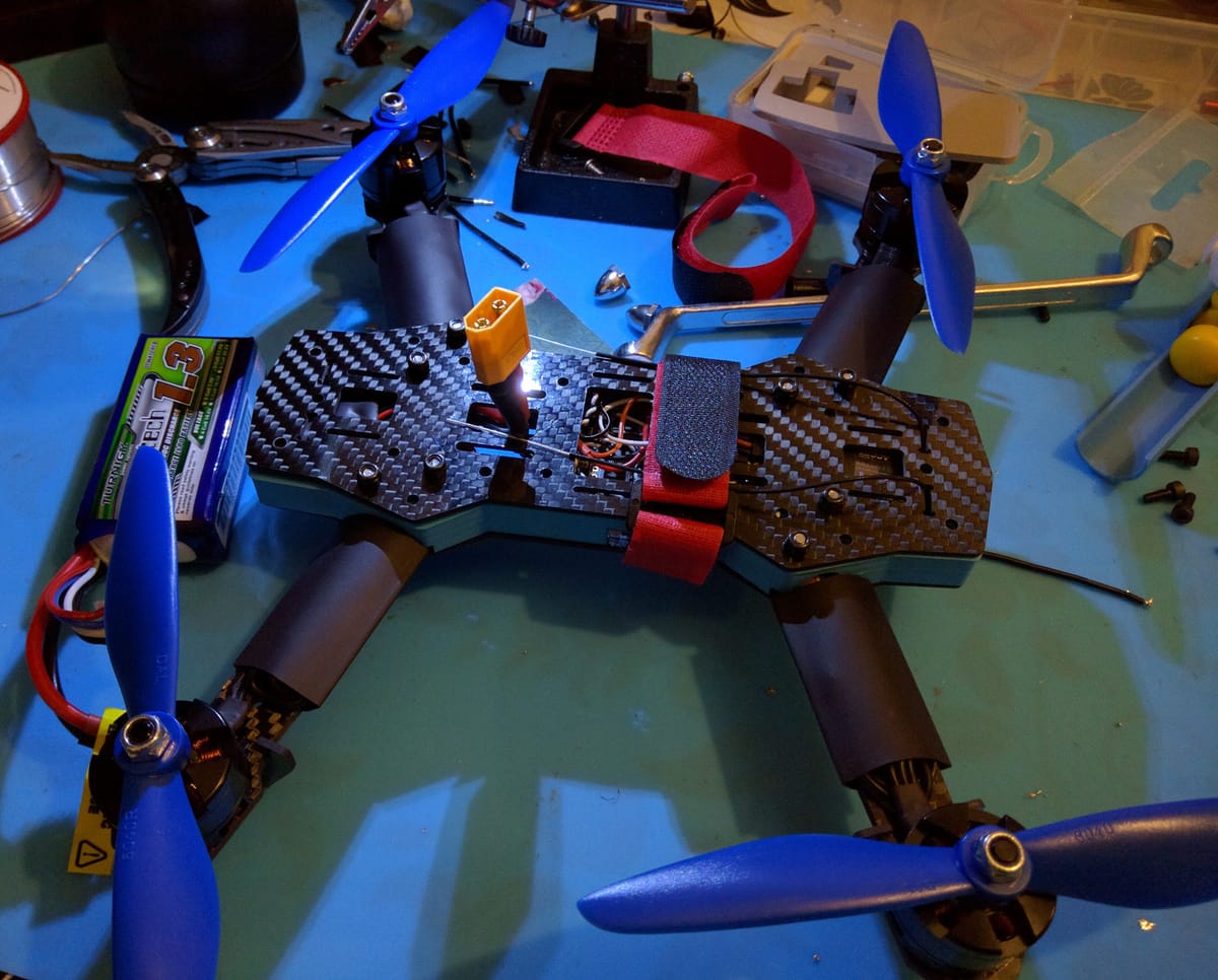
And here it is part assembled. I have not yet added the top plate as I am still working on it, adding LED strips and battery telemetry modules, etc.