ZMR250 Custom Tilting Foxeer FPV Camera Mount
A walk through of the design and 3D Printing of a custom tilting mount for the Foxier FPV camera for the popular ZMR250 quadcopter frame. Designed using OpenSCAD and Printed using an Original Utlimaker 3D Printer.

I ordered my FPV gear 2 weeks ago and so far, just the camera has shown up.
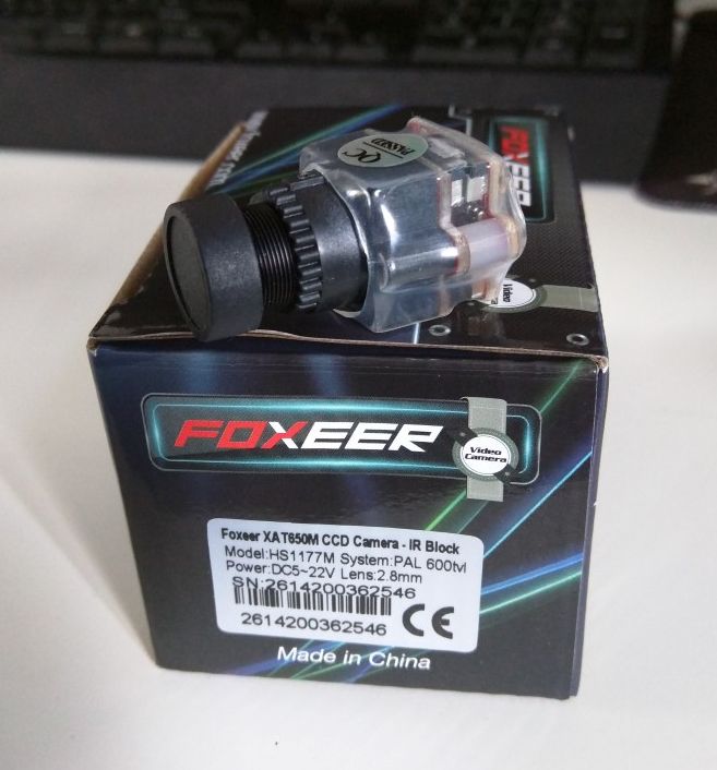
I decided to start working on the mounting mechanism for securing the camera to the quadcopter frame.
There are 3 main considerations:
- The camera needs to look forward.
- The camera will probably need to be tilted upwards slightly.
- The camera should be recessed into the frame so that it has some protection in the inevitable event of a crash.
There are many mounts available online. I had a look on Thingiverse and found many, but it was difficult to tell from the files what the measurements were and I really wanted to have a go at having it secured to the front two pillars. Securing things to pillars seemed to work well in may last post.
My first attempt was to have the tilting mechanism below or above the camera. This is a common design and enables a very simple angle locking mechanism.
This is what my first attempt looked like:
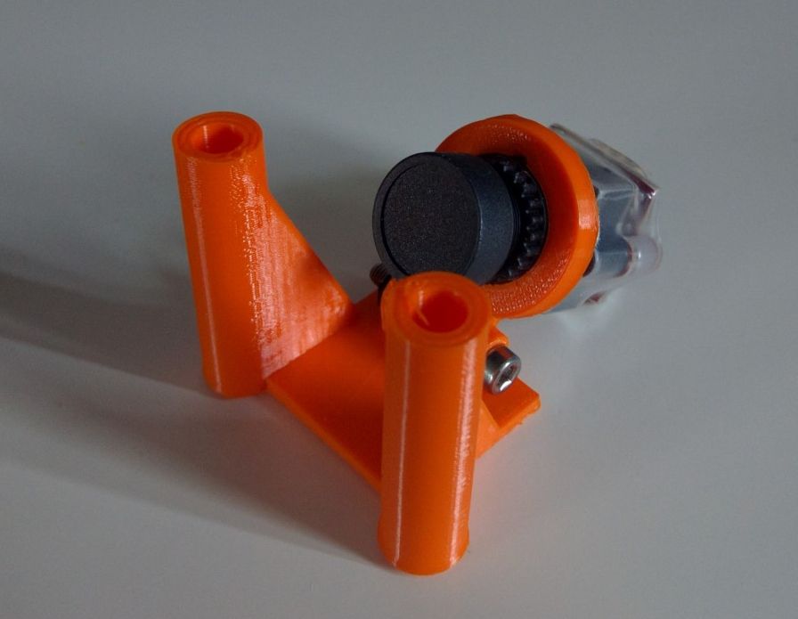
This did the job, but the hinge took up a lot of height and made the pivot point to far down, so that tilting was limited, the back would hit the top or bottom after only a few degrees.
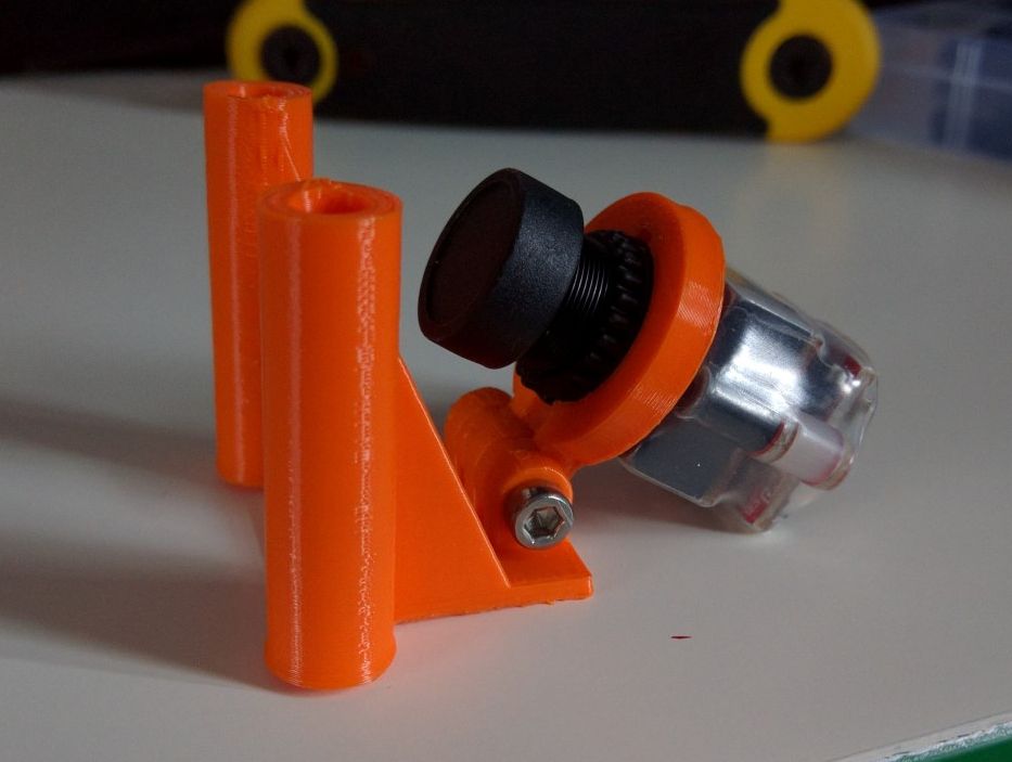
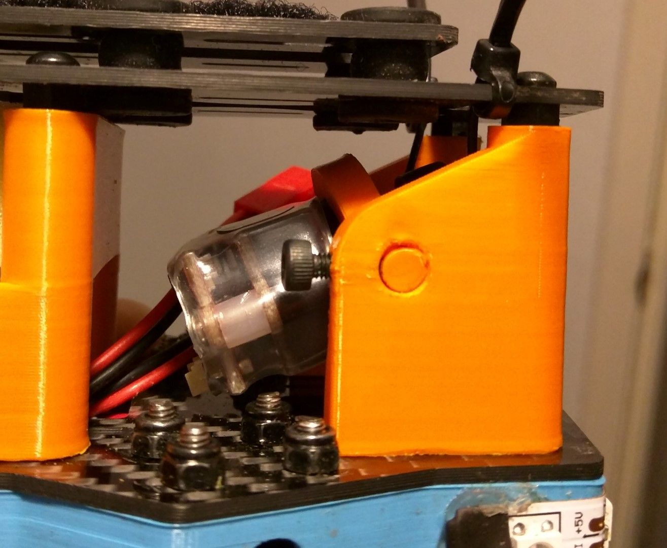
To solve this, I needed to move the pivot point to a more central location. The problem was the angle locking mechanism. I thought about it for a while and decided to have a rotating shaft and locking it with a perpendicular screw that pushes against it. Similar to that used on a shaft collar.
My first attempt had a solid base connecting the two walls of the design.
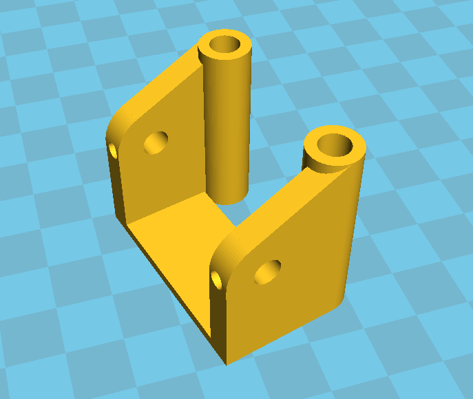
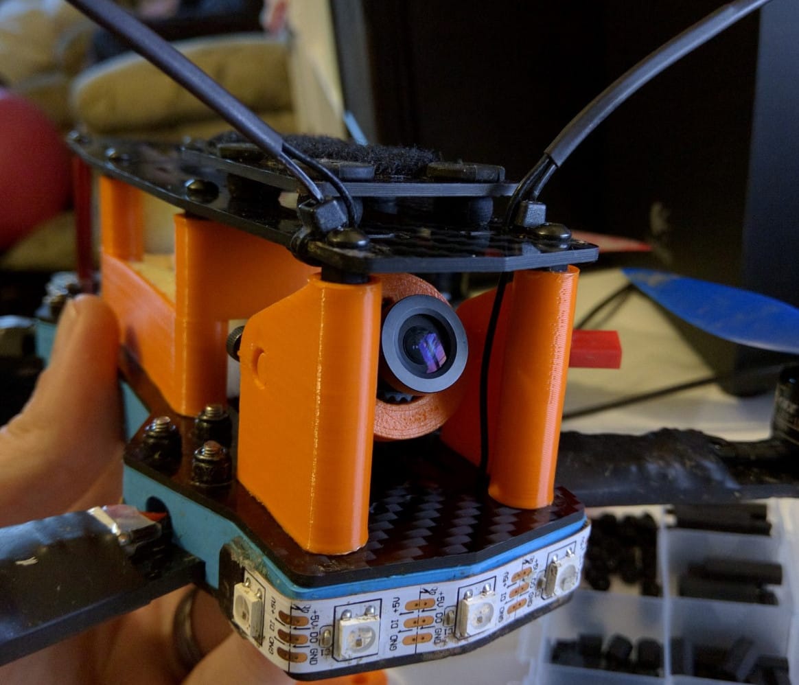
This made it more sturdy, but it was more difficult to get the camera ring in place. I ended up breaking one of these while trying to do just that. So I redesigned it as 2 separate halves.
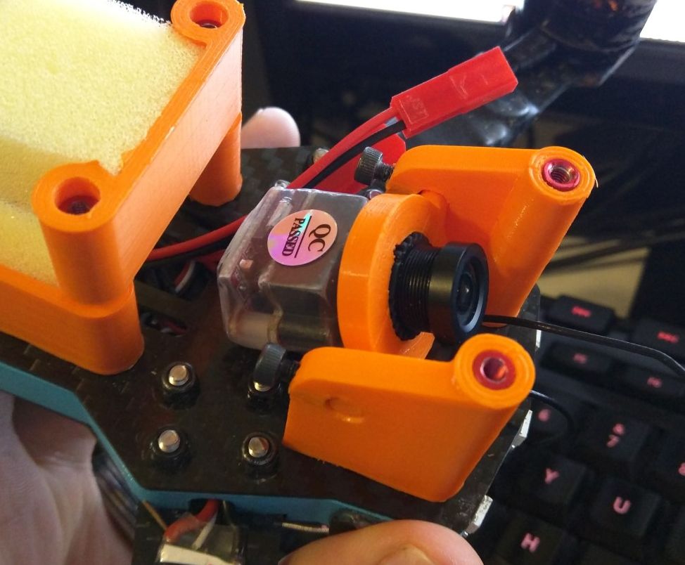
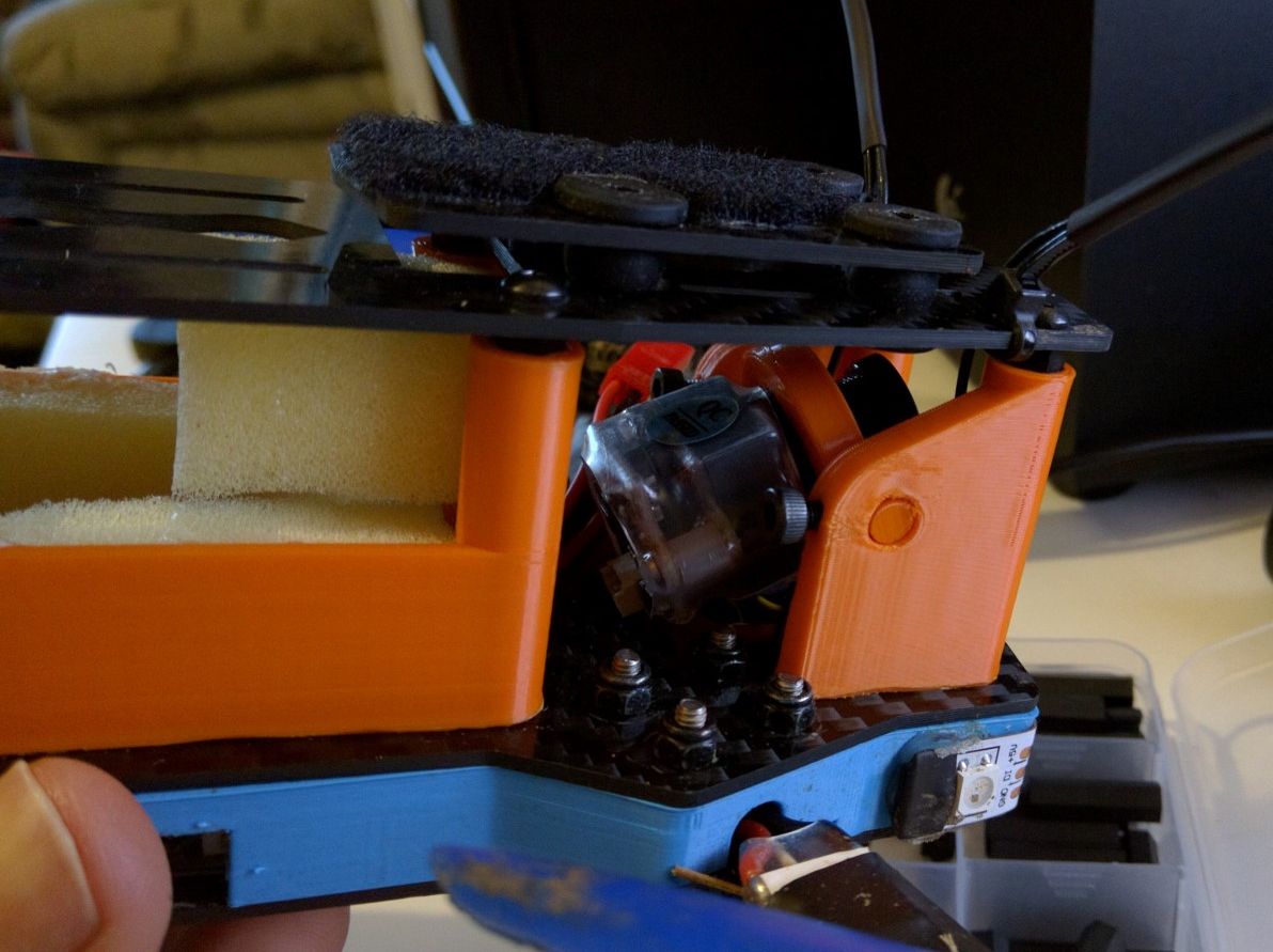

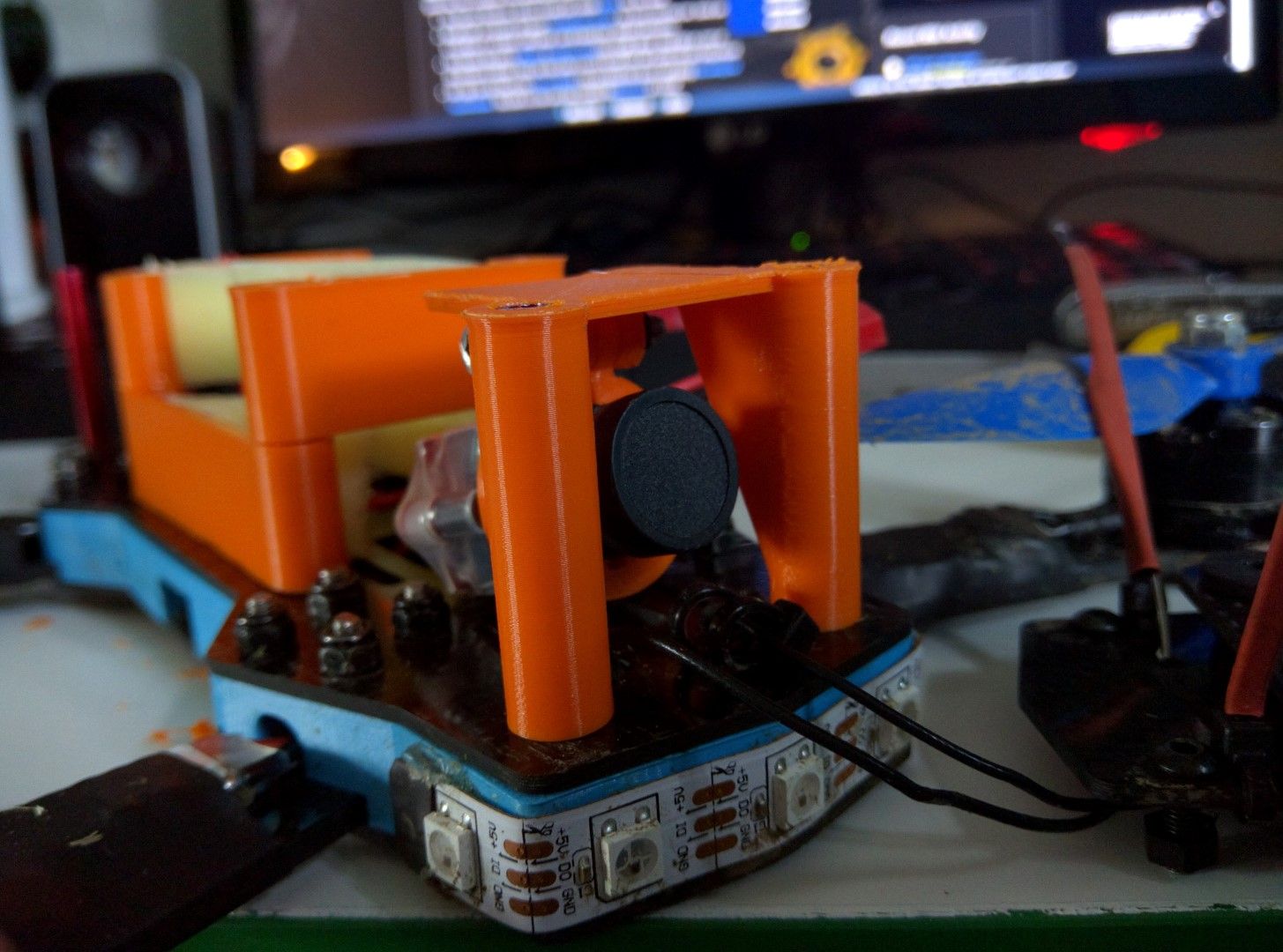
The new design seems to work well. The locking mechanism works well with 2 screws keeping it in place.
It has a much larger range of tilt.
I will have to wait until the rest of the gear has arrived to test it out properly, but it seems like it will do the job.
When designing these parts in OpenSCAD, I decided to store a lot more of the values as variables than last time, as I was called out by a friend for having so many magic numbers in the code. The last one was a lot simpler though and it didn't need as much modification. I don't think I could have done this one using magic numbers, it took a lot of tweaking to get right and is fairly complicated.
One of the things what was tricky was to connect the slant on the side pieces with the circle around the pivot point. I could have just shifted it by an arbitrary amount until it seemed to fit, but I wanted to make it automatically scale, if things need to be adjusted. I knew what I was looking for, but it took me a while to find it. My trigonometry is a bit rusty and I got stuck on my own, but managed to fine a way to get the tangent point and then I used that to make sure the slant always connects as a tangent to the circle. Check out the GitHub Gist to see how I managed that.
I designed this all from scratch in OpenSCAD.
I uploaded the OpenSCAD files to GitHub as a Gist.
I have uploaded the STL files to Thingiverse.
I printed them out on the Ultimaker on loan to Preston Hackspace.